Tag Archives: shaft steering

China Disc brake axle disc brake bridge trailer axle shaft outboard drum trailer steering axle axle bolt

Use: Trailer Parts, Trailer Areas
Parts: Trailer Axles
OE NO.: 523-551-5441
Max Payload: 2000lbs
Size: Common Dimension
Shade: Black
Title: Axle
Manufacturer: YAOLILAI
MOQ: 50pcs
Packaging Details: 1.The iron pallet with plastic film 2.Package according to the clients necessity
Port: HangZhou

Firm Data

HangZhou Huamei Weighty Sector Technology limited organization. is a collection of style and improvement, generation, sales, services as 1 of the medium-sized expert wheel production enterprises.The organization has a total manufacturing and testing products, with an outstanding creation management team. For a lot more than ten several years, the company constantly adhere to the consumer demand from customers as the item advancement centre, fully commited to creating individualized goods to meet up with the demands of client. The business constantly adhere to the “integrity, basic safety, worth-extra, earn-earn” advancement purposes, strong alliance, complementary rewards, Needle roller bearings for automobile NA4903 to satisfy market demand, product diversification progressively fashioned. And organization is committed to generating a global wheel goods extensive support platform Amongst them: wheel generation capacity contains: agricultural wheel rim,engineering wheel rim, mining equipment wheel rim, particular cars wheel rim, truck wheel rim and other 5 sequence of much more than three hundred types. The company always adhere to the “high quality wins the industry”, and has passed the “I S O 9 1 global good quality program certification”. Products are exported to the Center East, Europe, Africa, Southeast Asia, South The us, Grownup Electric powered Bike Ac Motor for Peugeot Scooters AJP Russia, Canada and other more than eighty nations around the world and locations.We will as often uphold the “good quality initial, popularity first” services basic principle, adhere to the “innovation and advancement” business philosophy, to accomplish social, company, person advantage, acquire-win! We sincerely welcome pals at residence and abroad to pay a visit to our factory, negotiate, CZPT cooperation and seek frequent improvement! Agricultural Gearboxes Agriculture bevel Gearbox For reducer T Appropriate Angle Pto For Agricultural gearbox

FAQ
1. How to promise consumers pursuits?
We have 360 diploma guarantee coverage:

  1. Following you authorized the sample, just before you location an purchase and spend for the deposit, you are welcomed to shell out a visit to our factories, we are confident that you will be significantly amazed by what we have and what we can do.
  2. Ahead of the delivery, we assist our clients to set up the third party to examine the quality of the goods,If mass manufacturing is not very same as approved sample, we will just take the totally accountability.
  3. If we do not ship on time, we will make up your decline.
  4. We cherish every clientele, each consumers can enjoy our VIP provider at any time.
two. How to solve the good quality difficulties after revenue?
  1. Take photographs of the issues and deliver to us
  2. Get videos of the problems and deliver to us
  3. Deliver back again the difficulty products, or we will sent our representitive for inspection.When we comfirmed its our difficulty, following interaction with clients, we will return the volume of issue merchandise, or cut this sum in subsequent order, and make new manufacturing and sent right away, or sent collectively with next order in accordance to customers’ Metal Shaft Collars Clamping Retaining Ring Shaft Sleeve Thrust Ring Throat Clamp Fastened Sleeve End Rings necessity.
three. How to confirm the high quality before mass creation?
  1. You can get a free of charge sample, and examine the good quality
  2. Ship us your samples, and we make the sample for your confirmation.

The Different Types of Axles

An axle is the central shaft of a gear or wheel. Axles are either fixed to the wheels or fixed to the vehicle. In some cases, they rotate together with the wheels and vehicle. The axle may also include bearings and mounting points. There are many types of axles, and it is important to understand the difference between each type.

Transaxle

The transaxle is the single mechanical device that combines the functions of a car’s differential, axle and transmission. It’s produced in manual and automatic models. A manual version is the preferred one for everyday driving, while an automatic one is more efficient in preventing vehicle damage. Here are some basics about the transaxle.
Transaxles are essential components of a car’s drivetrain, and any problems can cause major damage and leave the driver stranded. Transaxles include the transmission and the differential, which transfer the engine’s power to the wheels. Taking the time to check the transaxle is important to ensure that everything is functioning properly.
The transaxle is a very complex machine that combines the functions of the final drive and the transmission into one compact unit. The transaxle is a very versatile piece of automotive technology, and is an essential component of a front-wheel-drive car. In addition to conventional front-wheel-drive vehicles, many modern rear-wheel-drive vehicles use a transaxle to provide more even weight distribution.
The first American car to use a transaxle was the Cord 810 in the early 1920s. It was well ahead of its time, but was unsuccessful. For many years, the front-wheel drive automobile was absent from the United States automotive scene. It wasn’t until the 1960s that a front-wheel drive automobile re-emerged. A front-wheel-drive automobile, known as a transaxle, was the first to reach the market, and it’s not the only car to use this gearing.
A transaxle is a good option for vehicles with an extreme amount of torque. This system can handle powerful engine designs while keeping weight in the engine bay. It is not a perfect solution for all vehicles, however. In some vehicles, the extra weight added to the engine bay will affect the performance. The added weight will reduce traction. In addition, a transaxle mounts behind the engine, which adds weight to the rear.
Transaxles are the primary part of vehicles that have front-wheel drive. Their purpose is to transmit power from the engine to the drive wheels. The front-wheel-drive assembly had 2 short axles with complicated ball joints.
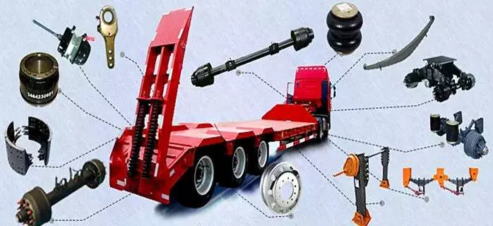
Axles

Full-floating axle

A full-floating axle is different from a semi-floating axle in several ways. A semi-floating axle is used for rear wheel drive cars, where it has a bearing mounted in the axle shaft. This axle supports the vehicle’s weight and transmits the drive torque from the transmission to the wheels. However, a semi-floating axle’s load capacity is limited by the size of the axle bearing. A full-floating axle, on the other hand, has the bearing mounted on the outside of the axle tube. The bearing is the only part of the axle that supports the vehicle, and the hub and bearing assembly are held together by a large nut.
The drive axle on a full-floating axle is splined at both ends so that it can easily be removed from the rear of a vehicle without removing the wheel. This type of axle makes it possible to change gears quickly and easily. Because of this, it’s not necessary to remove the wheels and tires in order to replace the axle. Instead, a common tool used to remove the axle from the wheel hub is an axle wrench.
Full-floating axles are more common in heavy-duty vehicles. The ability to carry heavy loads without causing the axle to break is a big advantage to full-floating axles. These axles require less maintenance and require less bends than traditional axles and may even be worth the extra investment if you have a heavy load to carry.
A full-floating axle allows the driver to change a broken axle shaft without having to remove the entire wheel. A full-floating axle will also allow the driver to remove the axle shaft without having to take off the wheel. Full-floating axles are also more durable than semi-floaters, which have weight resting on the axle tubes and housing.
While a full-floating axle is more expensive to manufacture, it is better for heavier vehicles that carry heavy loads. It is better to choose a full-floating axle if you have a heavy load or plan on towing.
Axles

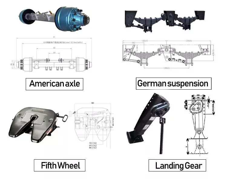
Three-quarter floater

A three-quarter floating axle is a type of floating axle that’s a compromise between the full and semi-floating types. Its bearings are located on the axle casing rather than on the hub, which means that it’s less susceptible to axle breakdown. However, it’s not as robust as a full floating axle.
This design combines the benefits of fully-floating axles with the simplicity of a semi-floating axle. Instead of having multiple wheel bearings, a single wheel bearing is installed in the center of the hub. The hub is then keyed rigidly to the axle shaft, providing a connecting connection and maintaining wheel alignment.
While a full-floating axle is the most common style of truck axle, you may see the three-quarter floater on the side of a pickup. It was common for 3/4-ton Gms to use these axles until the 1980s. Dodge and Ford also used a semi-float axle called a Dana 60. The difference between the two types of axles is the amount of support provided by the axleshaft and hub, and the number of lug nuts on the axleshaft and hub are different.
The three-quarter floater axle drive assembly of the present invention is illustrated in FIG. 1. The axle housing comprises an elongated axle tube 12, a hub member 30, and a hub shaft 16. A hub member 30 is rotatably supported on the axle tube 12 by an anti-friction bearing assembly 42. The axle shaft is retained in place by a domed plate 26.
This axle design has two main advantages. First, it transfers the weight of the vehicle to the axle casing. It also helps transfer the driving torque and side thrust to the wheel. This type of axle also has a differential cross shaft, which limits inward axial movement of the axle shaft.
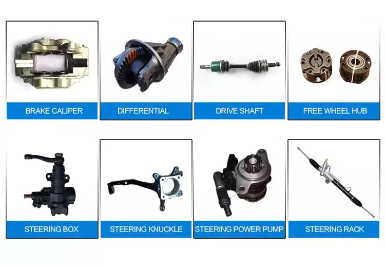
Axles

Dead axle

A Dead axle is a structural component that supports the rear wheel of a vehicle. It can either be straight or angled and is located behind the drive axle. Depending on the vehicle, the dead axle may be steerable. Tag axles are also common on agricultural equipment and certain heavy construction machinery. They are also known as lazy axles because they only contact the ground when a vehicle is carrying a significant load, thus saving tire wear. Dead axles may be rigid or flexible.
Some rear dead axles can also be configured as an air tank. The air is taken in and out of the rear dead axle through the port portions of the rear axle. This can reduce the size of the air tank. For this reason, it is a preferred design for rear dead axles. While most vehicles are equipped with two axles, the rear axle can be used to accommodate cargo.
FIG. 1 is a schematic plan view of a vehicle with two rear axles. The front axle is called the drive axle and the rear dead axle is called the dead axle. These components are located on a truck body frame. There are also battery and fuel tanks. They are used to distribute driving force from the front to rear wheels.
An axle is a crucial component of a vehicle. It transfers power from the engine to the wheels. A live axle is connected to the drive shaft and transmission, while a dead axle receives no direct power. This is the main difference between a live and dead axle. Although a dead axle is not as useful as a live one, it is still essential to understand what drives a car.
Dead axles are used in many vehicles for different purposes. Many large trucks are fitted with several of them for load bearing purposes. They also help distribute weight.
China Disc brake axle disc brake bridge trailer axle shaft outboard drum trailer steering axle     axle boltChina Disc brake axle disc brake bridge trailer axle shaft outboard drum trailer steering axle     axle bolt
editor by czh 2023-03-01

China wholesaler Hydraulic NBR Rubber Oil Cap Seal Power Steering Drive Shaft Oil Seal near me manufacturer

Product Description

01. Product Description

Product Description
Products Name Rubber O-ring & Oil sealing & Gasket
Products category rubber molded product
Material EPDM,NR,SBR,Nitrile, Silicone, Fluorosilicone, Neoprene, Urethane(PU), Polyacrylate(ACM), Ethylene Acrylic(AEM),  HNBR, Butyl(IIR), plastic like material (TPE, PU, NBR, silicone, NBR+TPE etc)
Size All size and thickness available.
Shape capable of all shapes as per drawing
Color Natural,black, Pantone code or RAL code, or as per client’s samples or requirements
Hardness 20°~90° Shore A, usually 30°~80° Shore A.
Surface finishing Texture (VDI/MT standard, or made to client’s sample), polished (high polish, mirror polish), smooth, painting, powder coating, printing, electroplating etc.
Drawing 2D or 3D draiwng in any image/picture format is OK
Free sample Yes
OEM/OEM Yes
Application Household, electronics, for vehicles like GM, Ford, Renault, Honda. Machinery, hospital, petrochemical, Military and Aerospace etc.
Market Europe, North America, Oceania
Quality certification ISO 90001:2008, TS16949, FDA, REACH, ROHS, SGS
QC Every order production will get more than 10 times regular check and 5 fives times random check by our professional QC. Or by Third party appointed by customer
 
Mold Molding Process Injection molding, mold processing, extrusion
Mould type processing mold, injection mold, extrusionmold
Machines 350T vacuum pressing machine and other pressing machine at 300T,250T and so on
Tooling equipment Rubber tension tester, Rubber vulcanization instrument, Durometer, calipers, ageing oven
Cavity 1~400 cavities
Mould Life 300,000~1,00,000 times
 
Production Production capacity finish each mold of product in 3 minutes and working on 3 shifts within 24 hours
Mold lead time 15~35 days
Sample lead time 3~5 days
Production time usually 15~30 days, should be confirmed before order
Loading port HangZhou, ZheJiang , HangZhou or as required

02. Company Profile

HangZhou Brother Rubber company was established in 1996 year, Located in HangZhou,China. We are an OEM/ODM professional manufacturer focused on solutions of rubber and plastic products. It represents high quality and is backed up by our team of quality assurance experts and our ISO 9001 and TS 16949 certifications. Its plant occupies over 2500 square meters of land.

Our main customers come from Europe,America and Oceanica, Example: UK, USA, Spain, Denmark,Germany, Australia, Finland .

Our strengths are our ability to respond quickly and efficiently to customer needs, excellent quality standards, and top notch follow-up service. Our strong engineering team supports our ability to provide excellent quality and on-time delivery. Our reputation is based on good credit, quality and service which is highly appreciated by customers in European and North American market. With mature and stable management team, advanced equipment and leading technology, experienced marketing team, a good reputation among our customers, the Group is making every effort to create the new brand of rubber, plastic products, metal products, mold processing in the world.

“leadship through quality and service, To create value for customers is creating a future for ourselves” as our motto. Welcome overseas friends to visit our company. Looking forward to your support more!

Office:
Our sale office is located in HangZhou city downtown, ZheJiang Province, China. It is in 2~3 hours drive distance to both our factory and airport or sea port in HangZhou. It is also convenient to meet customers from different countries.

Products and materials:
Our company is engaged in manufacture Rubber and plastic parts. The main products include molded rubber parts, Extrusion silicone tube/strip, silicone sponge tube, Injection plastic parts, Extrusion plastic parts, Rubber sponge parts, PVC dipping.

We make these parts according to the drawings or samples from customers with various shape,dimension and color , Example rubber rings, bellows, seals,hose,plug,bumper and so on, The main rubber raw material is EPDM,NR,SBR,Nitrile, Silicone, Fluorosilicone, Viton(FKM), Neoprene, Urethane(PU), Polyacrylate(ACM), Ethylene Acrylic(AEM), HNBR, Butyl(IIR) with 30~90 Shore A hardness. The main plastic raw material is PP, PA, PE, POM, PC, PVC, PS, PVC, TPE, TPR, TPU ,Santoprene. Especially we have advantage in rubber seals and auto rubber parts, We have produced many parts for some automotive enterprise like,Rover,BMW, Opel, GM, Ford, Renault, Honda.

Profound experience:
Our engineers and QC experts are engaged in rubber plastic industry over 23 years. Our core management team has rich experience and deep understanding of rubber and plastic development.

Production capacity:
Factory is working 24 hours by 3 shifts every day, It takes only 3 minutes to finish 1 mold of products. (If 1 mold has 50 cavities, then we can produce 50PCS of products within 3 minutes). Production machines including 350T vacuum pressing machine, 300T pressing machine, 250T machines and more others.

Quality control and test:
It has more than 10 times of quality check for every order, beginning from raw material check to package check. Every production line has at least 2 QC staff for random check and regular check. Test: manufactory testing machine includes rubber tension tester, rubber vulcanization instrument, durometer, calipers, ageing oven for Density test, Elongation at break, Bonding strength, Pulling force test, twisting force test, Rergarding other test like anti-high/low temperature which will be tested by Third Party Testing Center as customer required.

Sale service:
Every salesman should be in service after strictly trained with productions knowledge and customer-service requirements. Be skilled in exporting business procedure and English communication.


Calculating the Deflection of a Worm Shaft

In this article, we’ll discuss how to calculate the deflection of a worm gear’s worm shaft. We’ll also discuss the characteristics of a worm gear, including its tooth forces. And we’ll cover the important characteristics of a worm gear. Read on to learn more! Here are some things to consider before purchasing a worm gear. We hope you enjoy learning! After reading this article, you’ll be well-equipped to choose a worm gear to match your needs.
worm shaft

Calculation of worm shaft deflection

The main goal of the calculations is to determine the deflection of a worm. Worms are used to turn gears and mechanical devices. This type of transmission uses a worm. The worm diameter and the number of teeth are inputted into the calculation gradually. Then, a table with proper solutions is shown on the screen. After completing the table, you can then move on to the main calculation. You can change the strength parameters as well.
The maximum worm shaft deflection is calculated using the finite element method (FEM). The model has many parameters, including the size of the elements and boundary conditions. The results from these simulations are compared to the corresponding analytical values to calculate the maximum deflection. The result is a table that displays the maximum worm shaft deflection. The tables can be downloaded below. You can also find more information about the different deflection formulas and their applications.
The calculation method used by DIN EN 10084 is based on the hardened cemented worm of 16MnCr5. Then, you can use DIN EN 10084 (CuSn12Ni2-C-GZ) and DIN EN 1982 (CuAl10Fe5Ne5-C-GZ). Then, you can enter the worm face width, either manually or using the auto-suggest option.
Common methods for the calculation of worm shaft deflection provide a good approximation of deflection but do not account for geometric modifications on the worm. While Norgauer’s 2021 approach addresses these issues, it fails to account for the helical winding of the worm teeth and overestimates the stiffening effect of gearing. More sophisticated approaches are required for the efficient design of thin worm shafts.
Worm gears have a low noise and vibration compared to other types of mechanical devices. However, worm gears are often limited by the amount of wear that occurs on the softer worm wheel. Worm shaft deflection is a significant influencing factor for noise and wear. The calculation method for worm gear deflection is available in ISO/TR 14521, DIN 3996, and AGMA 6022.
The worm gear can be designed with a precise transmission ratio. The calculation involves dividing the transmission ratio between more stages in a gearbox. Power transmission input parameters affect the gearing properties, as well as the material of the worm/gear. To achieve a better efficiency, the worm/gear material should match the conditions that are to be experienced. The worm gear can be a self-locking transmission.
The worm gearbox contains several machine elements. The main contributors to the total power loss are the axial loads and bearing losses on the worm shaft. Hence, different bearing configurations are studied. One type includes locating/non-locating bearing arrangements. The other is tapered roller bearings. The worm gear drives are considered when locating versus non-locating bearings. The analysis of worm gear drives is also an investigation of the X-arrangement and four-point contact bearings.
worm shaft

Influence of tooth forces on bending stiffness of a worm gear

The bending stiffness of a worm gear is dependent on tooth forces. Tooth forces increase as the power density increases, but this also leads to increased worm shaft deflection. The resulting deflection can affect efficiency, wear load capacity, and NVH behavior. Continuous improvements in bronze materials, lubricants, and manufacturing quality have enabled worm gear manufacturers to produce increasingly high power densities.
Standardized calculation methods take into account the supporting effect of the toothing on the worm shaft. However, overhung worm gears are not included in the calculation. In addition, the toothing area is not taken into account unless the shaft is designed next to the worm gear. Similarly, the root diameter is treated as the equivalent bending diameter, but this ignores the supporting effect of the worm toothing.
A generalized formula is provided to estimate the STE contribution to vibratory excitation. The results are applicable to any gear with a meshing pattern. It is recommended that engineers test different meshing methods to obtain more accurate results. One way to test tooth-meshing surfaces is to use a finite element stress and mesh subprogram. This software will measure tooth-bending stresses under dynamic loads.
The effect of tooth-brushing and lubricant on bending stiffness can be achieved by increasing the pressure angle of the worm pair. This can reduce tooth bending stresses in the worm gear. A further method is to add a load-loaded tooth-contact analysis (CCTA). This is also used to analyze mismatched ZC1 worm drive. The results obtained with the technique have been widely applied to various types of gearing.
In this study, we found that the ring gear’s bending stiffness is highly influenced by the teeth. The chamfered root of the ring gear is larger than the slot width. Thus, the ring gear’s bending stiffness varies with its tooth width, which increases with the ring wall thickness. Furthermore, a variation in the ring wall thickness of the worm gear causes a greater deviation from the design specification.
To understand the impact of the teeth on the bending stiffness of a worm gear, it is important to know the root shape. Involute teeth are susceptible to bending stress and can break under extreme conditions. A tooth-breakage analysis can control this by determining the root shape and the bending stiffness. The optimization of the root shape directly on the final gear minimizes the bending stress in the involute teeth.
The influence of tooth forces on the bending stiffness of a worm gear was investigated using the CZPT Spiral Bevel Gear Test Facility. In this study, multiple teeth of a spiral bevel pinion were instrumented with strain gages and tested at speeds ranging from static to 14400 RPM. The tests were performed with power levels as high as 540 kW. The results obtained were compared with the analysis of a three-dimensional finite element model.
worm shaft

Characteristics of worm gears

Worm gears are unique types of gears. They feature a variety of characteristics and applications. This article will examine the characteristics and benefits of worm gears. Then, we’ll examine the common applications of worm gears. Let’s take a look! Before we dive in to worm gears, let’s review their capabilities. Hopefully, you’ll see how versatile these gears are.
A worm gear can achieve massive reduction ratios with little effort. By adding circumference to the wheel, the worm can greatly increase its torque and decrease its speed. Conventional gearsets require multiple reductions to achieve the same reduction ratio. Worm gears have fewer moving parts, so there are fewer places for failure. However, they can’t reverse the direction of power. This is because the friction between the worm and wheel makes it impossible to move the worm backwards.
Worm gears are widely used in elevators, hoists, and lifts. They are particularly useful in applications where stopping speed is critical. They can be incorporated with smaller brakes to ensure safety, but shouldn’t be relied upon as a primary braking system. Generally, they are self-locking, so they are a good choice for many applications. They also have many benefits, including increased efficiency and safety.
Worm gears are designed to achieve a specific reduction ratio. They are typically arranged between the input and output shafts of a motor and a load. The 2 shafts are often positioned at an angle that ensures proper alignment. Worm gear gears have a center spacing of a frame size. The center spacing of the gear and worm shaft determines the axial pitch. For instance, if the gearsets are set at a radial distance, a smaller outer diameter is necessary.
Worm gears’ sliding contact reduces efficiency. But it also ensures quiet operation. The sliding action limits the efficiency of worm gears to 30% to 50%. A few techniques are introduced herein to minimize friction and to produce good entrance and exit gaps. You’ll soon see why they’re such a versatile choice for your needs! So, if you’re considering purchasing a worm gear, make sure you read this article to learn more about its characteristics!
An embodiment of a worm gear is described in FIGS. 19 and 20. An alternate embodiment of the system uses a single motor and a single worm 153. The worm 153 turns a gear which drives an arm 152. The arm 152, in turn, moves the lens/mirr assembly 10 by varying the elevation angle. The motor control unit 114 then tracks the elevation angle of the lens/mirr assembly 10 in relation to the reference position.
The worm wheel and worm are both made of metal. However, the brass worm and wheel are made of brass, which is a yellow metal. Their lubricant selections are more flexible, but they’re limited by additive restrictions due to their yellow metal. Plastic on metal worm gears are generally found in light load applications. The lubricant used depends on the type of plastic, as many types of plastics react to hydrocarbons found in regular lubricant. For this reason, you need a non-reactive lubricant.

China wholesaler Hydraulic NBR Rubber Oil Cap Seal Power Steering Drive Shaft Oil Seal   near me manufacturer China wholesaler Hydraulic NBR Rubber Oil Cap Seal Power Steering Drive Shaft Oil Seal   near me manufacturer

China Good quality Cardan Shaft Tractor Pto Drive Power Take off Agricultural Transmission Manufacturing Heavy-Duty Farm Steering Industries Best Telescopic Cross Joints Shaft wholesaler

Product Description

Cardan Shaft Tractor Pto Drive Power Take off Agricultural Transmission Manufacturing Heavy-Duty Farm Steering Industries Best Telescopic Cross Joints Shaft

EPT Cardan Shafts, or even called u-joints, facilitate reliable torque transfer between spatially remote drive and output trains. Cardan shafts from CZPT offer suitable mechanical drive solutions in nearly all industrial sectors due to their versatile design and their high efficiency.

Our weight-optimised, energy-efficient, high-performance universal joint shafts are developed by using advanced methods and FEM calculations to provide optimal tube wall strengths and diameters for high torsion and bending resistance.

We use tempered steel and case-hardened steel for our u-joints. Calibrated precision steel tubes are used for particularly demanding solutions. All materials used fulfil the requirements for marine classification and rail vehicle applications. Reliable and continuous operation of our u-joints with a high torque capacity is therefore guaranteed. Our Cardan shafts are further characterised by low-maintenance components and low maintenance costs over the entire product life cycle.

The Functions of Splined Shaft Bearings

Splined shafts are the most common types of bearings for machine tools. They are made of a wide variety of materials, including metals and non-metals such as Delrin and nylon. They are often fabricated to reduce deflection. The tooth profile will become deformed with time, as the shaft is used over a long period of time. Splined shafts are available in a huge range of materials and lengths.

Functions

Splined shafts are used in a variety of applications and industries. They are an effective anti-rotational device, as well as a reliable means of transmitting torque. Other types of shafts are available, including key shafts, but splines are the most convenient for transmitting torque. The following article discusses the functions of splines and why they are a superior choice. Listed below are a few examples of applications and industries in which splines are used.
Splined shafts can be of several styles, depending on the application and mechanical system in question. The differences between splined shaft styles include the design of teeth, overall strength, transfer of rotational concentricity, sliding ability, and misalignment tolerance. Listed below are a few examples of splines, as well as some of their benefits. The difference between these styles is not mutually exclusive; instead, each style has a distinct set of pros and cons.
A splined shaft is a cylindrical shaft with teeth or ridges that correspond to a specific angular position. This allows a shaft to transfer torque while maintaining angular correspondence between tracks. A splined shaft is defined as a cylindrical member with several grooves cut into its circumference. These grooves are equally spaced around the shaft and form a series of projecting keys. These features give the shaft a rounded appearance and allow it to fit perfectly into a grooved cylindrical member.
While the most common applications of splines are for shortening or extending shafts, they can also be used to secure mechanical assemblies. An “involute spline” spline has a groove that is wider than its counterparts. The result is that a splined shaft will resist separation during operation. They are an ideal choice for applications where deflection is an issue.
A spline shaft’s radial torsion load distribution is equally distributed, unless a bevel gear is used. The radial torsion load is evenly distributed and will not exert significant load concentration. If the spline couplings are not aligned correctly, the spline connection can fail quickly, causing significant fretting fatigue and wear. A couple of papers discuss this issue in more detail.
splineshaft

Types

There are many different types of splined shafts. Each type features an evenly spaced helix of grooves on its outer surface. These grooves are either parallel or involute. Their shape allows them to be paired with gears and interchange rotary and linear motion. Splines are often cold-rolled or cut. The latter has increased strength compared to cut spines. These types of shafts are commonly used in applications requiring high strength, accuracy, and smoothness.
Another difference between internal and external splined shafts lies in the manufacturing process. The former is made of wood, while the latter is made of steel or a metal alloy. The process of manufacturing splined shafts involves cutting furrows into the surface of the material. Both processes are expensive and require expert skill. The main advantage of splined shafts is their adaptability to a wide range of applications.
In general, splined shafts are used in machinery where the rotation is transferred to an internal splined member. This member can be a gear or some other rotary device. These types of shafts are often packaged together as a hub assembly. Cleaning and lubricating are essential to the life of these components. If you’re using them on a daily basis, you’ll want to make sure to regularly inspect them.
Crowned splines are usually involute. The teeth of these splines form a spiral pattern. They are used for smaller diameter shafts because they add strength. Involute splines are also used on instrument drives and valve shafts. Serration standards are found in the SAE. Both kinds of splines can also contain a ball bearing for high torque. The difference between the 2 types of splines is the number of teeth on the shaft.
Internal splines have many advantages over external ones. For example, an internal spline shaft can be made using a grinding wheel instead of a CNC machine. It also uses a more accurate and economical process. Furthermore, it allows for a shorter manufacturing cycle, which is essential when splining high-speed machines. In addition, it stabilizes the relative phase between the spline and thread.
splineshaft

Manufacturing methods

There are several methods used to fabricate a splined shaft. Key and splined shafts are constructed from 2 separate parts that are shaped in a synchronized manner to transfer torque uniformly. Hot rolling is 1 method, while cold rolling utilizes low temperatures to form metal. Both methods enhance mechanical properties, surface finishes, and precision. The advantage of cold rolling is its cost-effectiveness.
Cold forming is 1 method, as well as machining and assembling. Cold forming is a unique process that allows the spline to be shaped to the desired shape. The resulting shape provides maximum contact area and torsional strength. Standard splines are available in standard sizes, but custom lengths can also be ordered. CZPT offers various auxiliary equipment, such as mating sleeves and flanged bushings.
Cold forging is another method. This method produces long splined shafts that are used in automobile propellers. After the spline portion is cut out, it is worked on in a hobbing machine. Work hardening enhances the root strength of the splined portion. It can be used for bearings, gears, and other mechanical components. Listed below are the manufacturing methods for splined shafts.
Parallel splines are the simplest of the splined shaft manufacturing methods. Parallel splines are usually welded to shafts, while involute splines are made of metal or non-metals. Splines are available in a wide variety of lengths and materials. The process is usually accompanied by a process called milling. The workpiece rotates to produce the serrated surface.
Splines are internal or external grooves in a splined shaft. They work in combination with keyways to transfer torque. Male and female splines are used in gears. Female and male splines correspond to 1 another to ensure proper angular correspondence. Involute splines have more surface area and thus are stronger than external splines. Moreover, they help the shaft fit into a grooved cylindrical member without misalignment.
A variety of other methods of manufacturing a splined shaft can be used to produce a splined shaft. Spline shafts can be produced using broaching and shaping, 2 precision machining methods. Broaching uses a metal tool with successively larger teeth to remove metal and create ridges and holes in the surface of a material. However, this process is expensive and requires special expertise.
splineshaft

Applications

The splined shaft is a mechanical component with a helix-like shape formed by the equal spacing of grooves in a circular ring. The splines can either have parallel or involute sides. The splines minimize stress concentration in stationary joints and can be used in both rotary and linear motion. In some cases, splines are rolled rather than cut. The latter is more durable than cut splines and is often used in applications requiring high strength, accuracy, and smooth finish.
Splined shafts are commonly made of carbon steel. This alloy steel has a low carbon content, making it easy to work with. Carbon steel is a great choice for splines because it is malleable. Generally, high-quality carbon steel provides a consistent motion. Steel alloys are also available that contain nickel, chromium, copper, and other metals. If you’re unsure of the right material for your application, you can consult a spline chart.
Splines are a versatile mechanical component. They are easy to cut and fit. Splines can be internal or external, with teeth positioned at equal intervals on both sides of the shaft. This allows the shaft to engage with the hub around the entire circumference of the hub. It also increases load capacity by creating a constant multiple-tooth point of contact with the hub. For this reason, they’re used extensively in rotary and linear motion.
Splined shafts are used in a wide variety of industries. CZPT Inc. offers custom and standard splined shafts for a variety of applications. When choosing a splined shaft for a specific application, consider the surrounding mated components, torque requirements, and size requirements. These 3 factors will make it the ideal choice for your rotary equipment. And you’ll be pleased with the end result!
There are many types of splines and their applications are endless. They transfer torque and angular misalignment between parts, and they also enable the axial rotation of assembled components. Therefore, splines are an essential component of machinery and are used in a wide range of applications. This type of shaft can be found in various types of machines, from household appliances to industrial machinery. So, the next time you’re looking for a splined shaft, make sure you look for a splined one.

China Good quality Cardan Shaft Tractor Pto Drive Power Take off Agricultural Transmission Manufacturing Heavy-Duty Farm Steering Industries Best Telescopic Cross Joints Shaft   wholesaler China Good quality Cardan Shaft Tractor Pto Drive Power Take off Agricultural Transmission Manufacturing Heavy-Duty Farm Steering Industries Best Telescopic Cross Joints Shaft   wholesaler